

Week 09. has arrive, this week I have new assignments and new equipment that i'm going to use. So, to begin i'm going to give some information, as usual, about the machines and components that i'll be using to get through the assingments of this week. During this week is all about outout devices, PCB board and a little programming. For this weeks assignments i'm using the voltmeter and the oscilloscope. So let´s begin with this week assignments and as usual hoping for the best and trying to enjoy!.
This week assignmets are:
Group assignments:
Individual assignments:
| Machines/Equipment | Components |
|---|---|
|
|
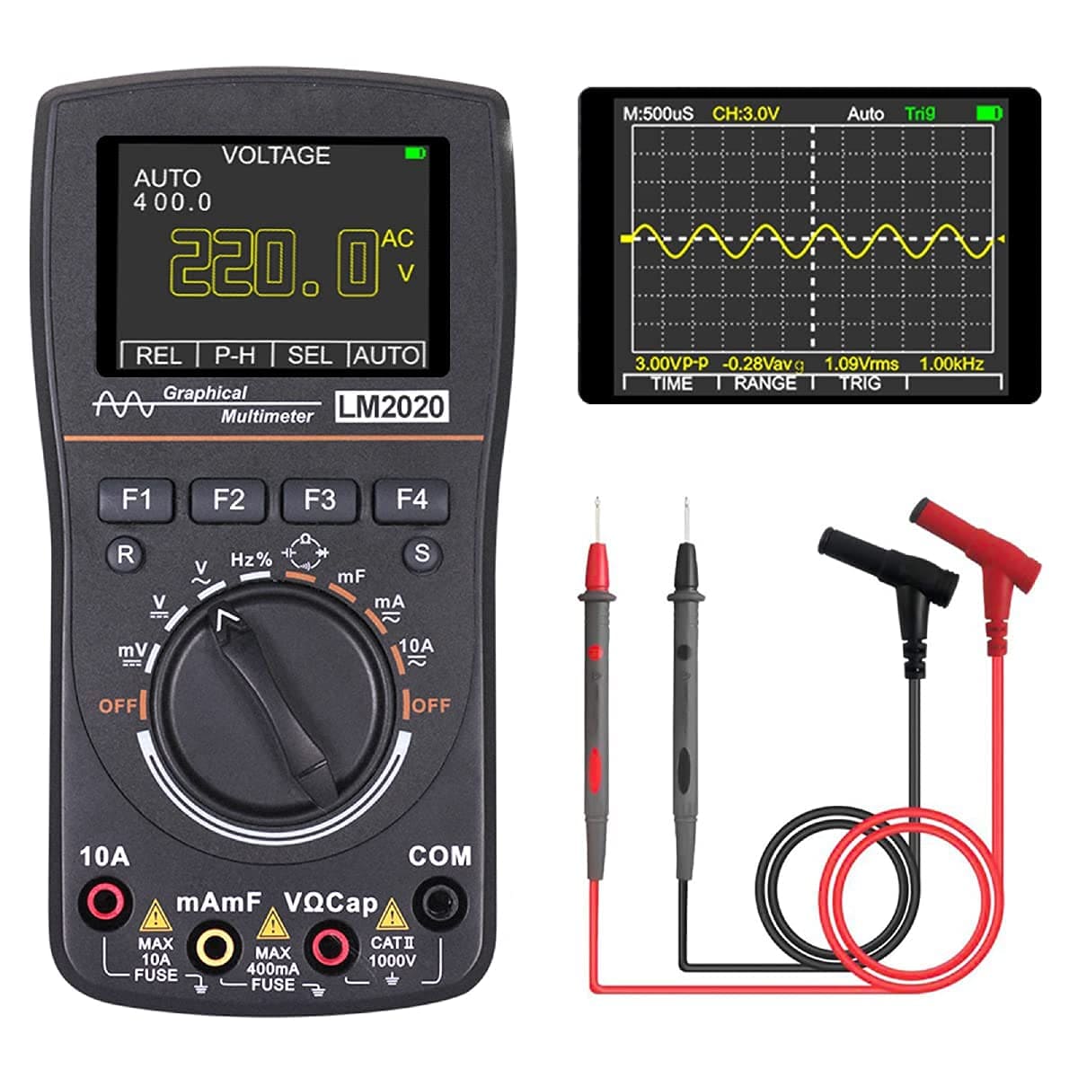
Multimeter
A digital multimeter (DMM) is a versatile electronic device used to measure various electrical properties, including voltage, current, and resistance. The device displays the measurements on a digital screen, making it easy to read and understand the results accurately. Digital multimeters have replaced traditional analog meters and offer higher accuracy, reliability, and better handling of impedance.
A multimeter is used to troubleshoot electrical problems on motors, circuits, power supplies, and switches. It is the most common tool used by technicians to troubleshoot electrical issues. A few examples of use cases are:
Data from: Multimeter
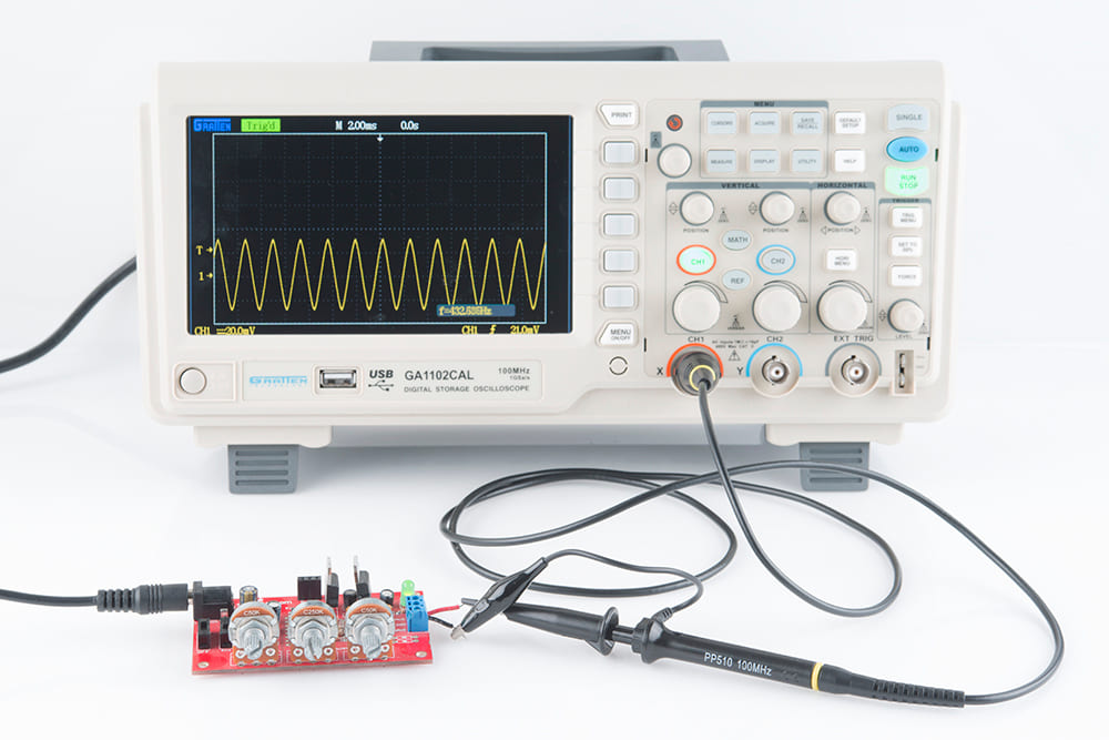
Oscilloscope
Is a tool that displays electric voltage signals over time as a waveform graph. The vertical axis (Y) represents the voltage measurement, and the horizontal axis (X) represents time. Sometimes, a Z-axis is displayed as color grades or brightness that represents the intensity of the voltage. The voltage signals are displayed as wavelengths oscillating or repeating variations over time. While oscilloscopes are most commonly used by engineers or electrical technicians, most people will see oscilloscopes in the medical field, whether in person or through movies or television. Typically, the oscilloscope displays a medical patient's heartbeat or brain waves.
Data from: Oscilloscope

The SSD1306 display is an OLED that is controlled by the SSD1306 micro-chip driver, which acts as a bridge between the display matrix and the microcontroller. Despite the size, these displays are very functional and capable of displaying complex images.
Data from: LCD screen

Is a widely used standard source of light in electrical equipment. It has a wide range of applications ranging from your mobile phone to large advertising billboards. They mostly find applications in devices that show the time and display different types of data.
Data from: Leds
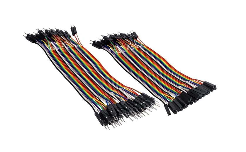
Also called Jumper Wire cables. Are electrical wires, or group of them in a cable, with a connector or pins at each end. They are used to connect hardware such as sensors, Arduino boards, and breadboards together.
Data from: Dupont wire
Pulse Width Modulation, or PWM, is a technique for getting analog results with digital means. Digital control is used to create a square wave, a signal switched between on and off. This on-off pattern can simulate voltages in between the full Vcc of the board (e.g., 5 V on UNO, 3.3 V on a MKR board) and off (0 Volts) by changing the portion of the time the signal spends on versus the time that the signal spends off. The duration of "on time" is called the pulse width. To get varying analog values, you change, or modulate, that pulse width. If you repeat this on-off pattern fast enough with an LED for example, the result is as if the signal is a steady voltage between 0 and Vcc controlling the brightness of the LED.
In the graphic below, the green lines represent a regular time period. This duration or period is the inverse of the PWM frequency. In other words, with Arduino's PWM frequency at about 500Hz, the green lines would measure 2 milliseconds each. A call to analogWrite() is on a scale of 0 - 255, such that analogWrite(255) requests a 100% duty cycle (always on), and analogWrite(127) is a 50% duty cycle (on half the time) for example.
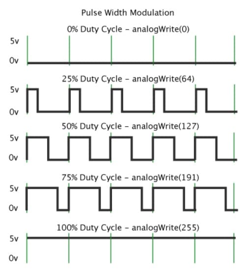
Data from: PWM
A pulse width modulating signal is generated using a comparator. The modulating signal forms one part of the input to the comparator, while the non-sinusoidal wave or sawtooth wave forms the other part of the input. The comparator compares two signals and generates a PWM signal as its output waveform.

If the sawtooth signal is more than the modulating signal, then the output signal is in a “High” state. The value of the magnitude determines the comparator output which defines the width of the pulse generated at the output.
Data from: PWM signal
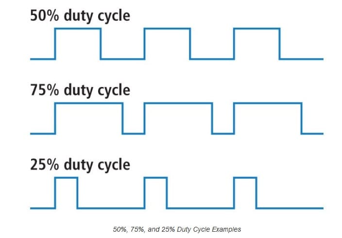
When the signal is high, we call this "on time". To describe the amount of "on time" , we use the concept of duty cycle. Duty cycle is measured in percentage. The percentage duty cycle specifically describes the percentage of time a digital signal is on over an interval or period of time. This period is the inverse of the frequency of the waveform. If a digital signal spends half of the time on and the other half off, we would say the digital signal has a duty cycle of 50% and resembles an ideal square wave. If the percentage is higher than 50%, the digital signal spends more time in the high state than the low state and vice versa if the duty cycle is less than 50%. Here is a graph that illustrates these three scenarios:
100% duty cycle would be the same as setting the voltage to 5 Volts (high). 0% duty cycle would be the same as grounding the signal.
Data from: Duty cycle
A PWM signal stays “ON” for a given time and stays “OFF” for a certain time. The percentage of time for which the signal remains “ON” is known as the duty cycle. If the signal is always “ON,” then the signal must have a 100 % duty cycle. The formula to calculate the duty cycle is given as follows:

The average value of the voltage depends on the duty cycle. As a result, the average value can be varied by controlling the width of the “ON” of a pulse.
The frequency of PWM determines how fast a PWM completes a period. The frequency of a pulse is shown in the figure below. The frequency of PWM can be calculated as follows:
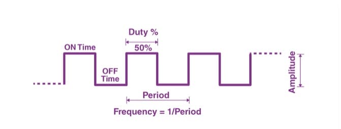
The output voltage of the PWM signal will be the percentage of the duty cycle. For example, for a 100% duty cycle, if the operating voltage is 5 V then the output voltage will also be 5 V. If the duty cycle is 50%, then the output voltage will be 2.5 V.
Data from: About PWM
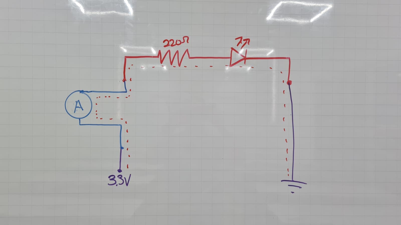
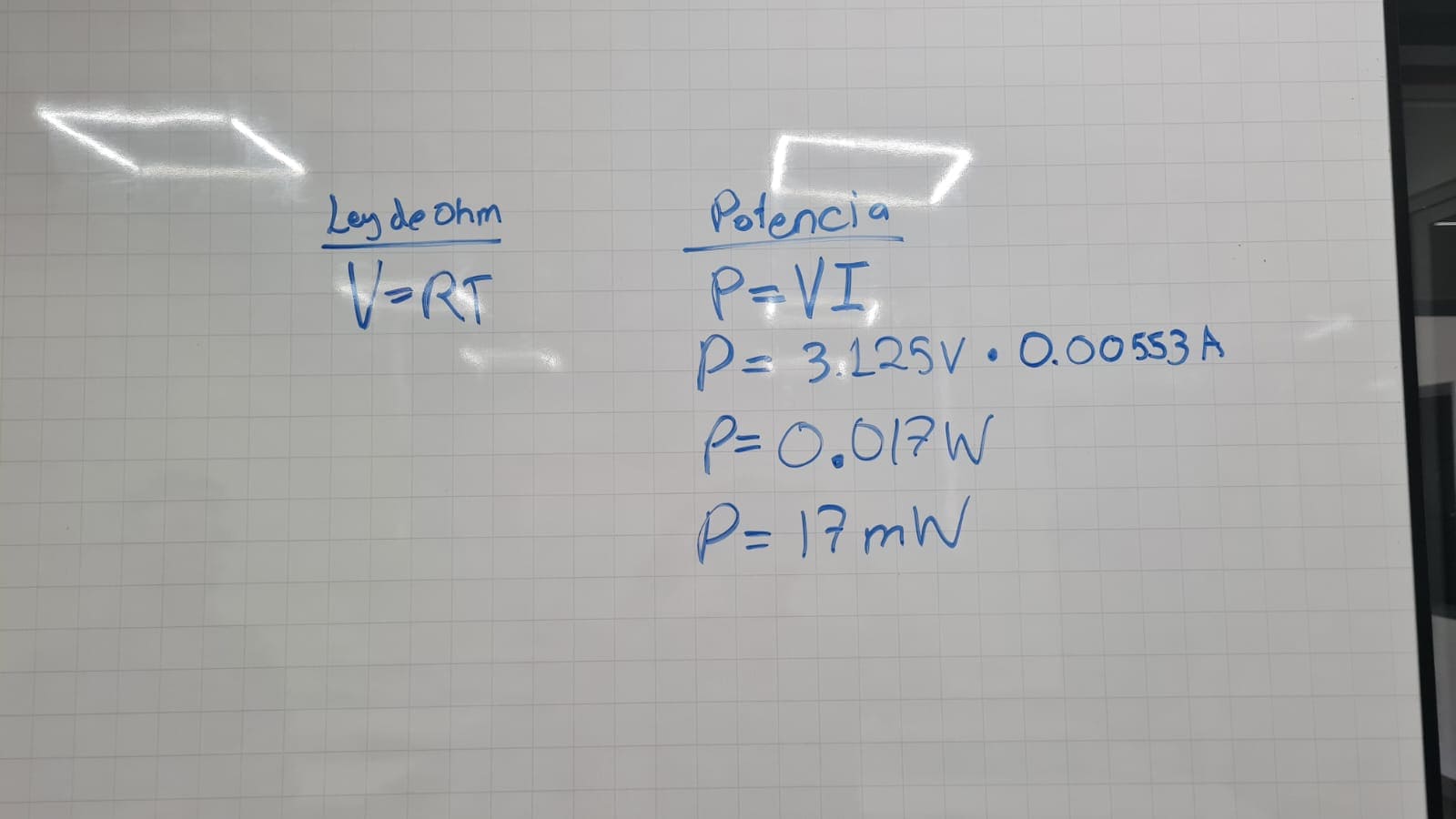
Now that i've learn a few things about PWM i'm using a multimeter and oscilloscope to do the measures. So lets take a look at the results. But before I take the measures of the power consumption of the output devices, it's important to learn about Ohm's law:
Ohm’s law states the relationship between electric current and potential difference. The current that flows through most conductors is directly proportional to the voltage applied to it. Georg Simon Ohm, a German physicist was the first to verify Ohm’s law experimentally. Ohm’s law states that the voltage across a conductor is directly proportional to the current flowing through it, provided all physical conditions and temperatures remain constant.
Data from: About Ohm's Law
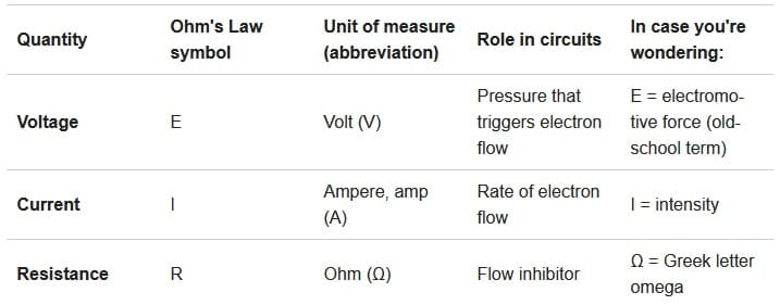
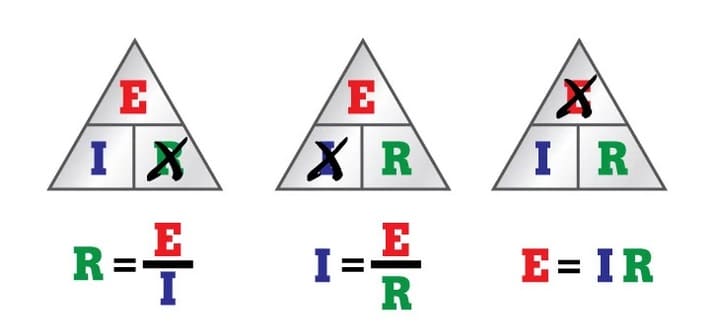
Ohm's Law is a formula used to calculate the relationship between voltage, current and resistance in an electrical circuit: E = I x R , when spelled out, it means:
Data from: Learning about Ohm's law
Before I took the measures I need to have ready my circuit, remember that for this assignments i'm using the PCB board and circuit I design in week 08. I've consider two different codes, the first one makes the led flashes and the second is sending a text to a Oled screen.
In this first results im using the flashing led code and input a 1.65 voltage:
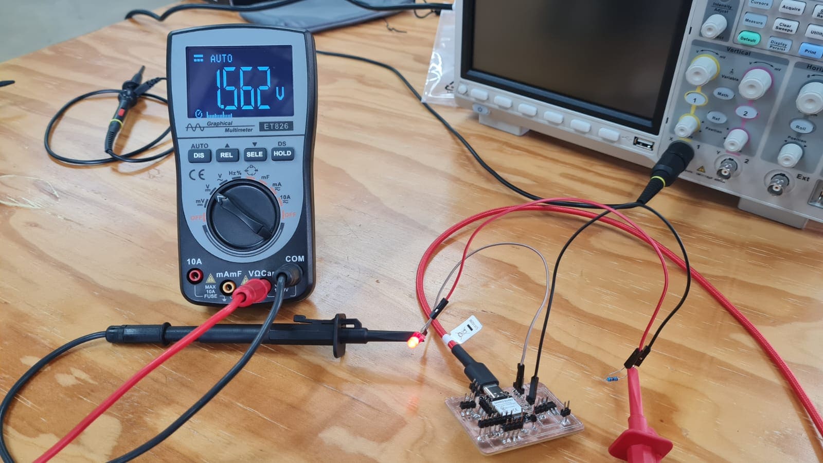
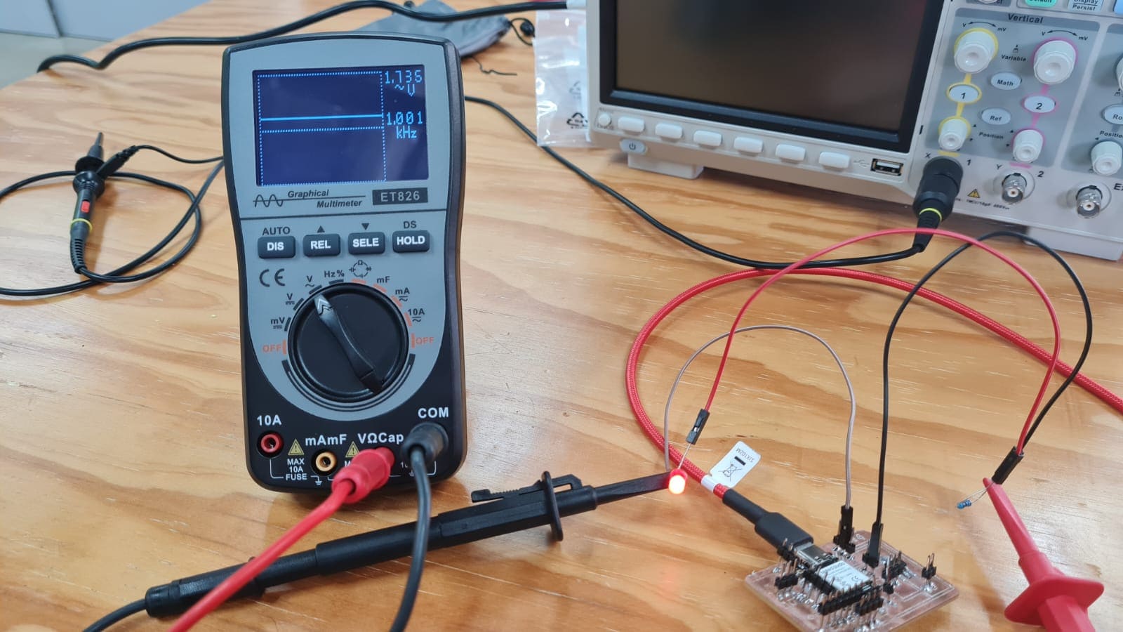
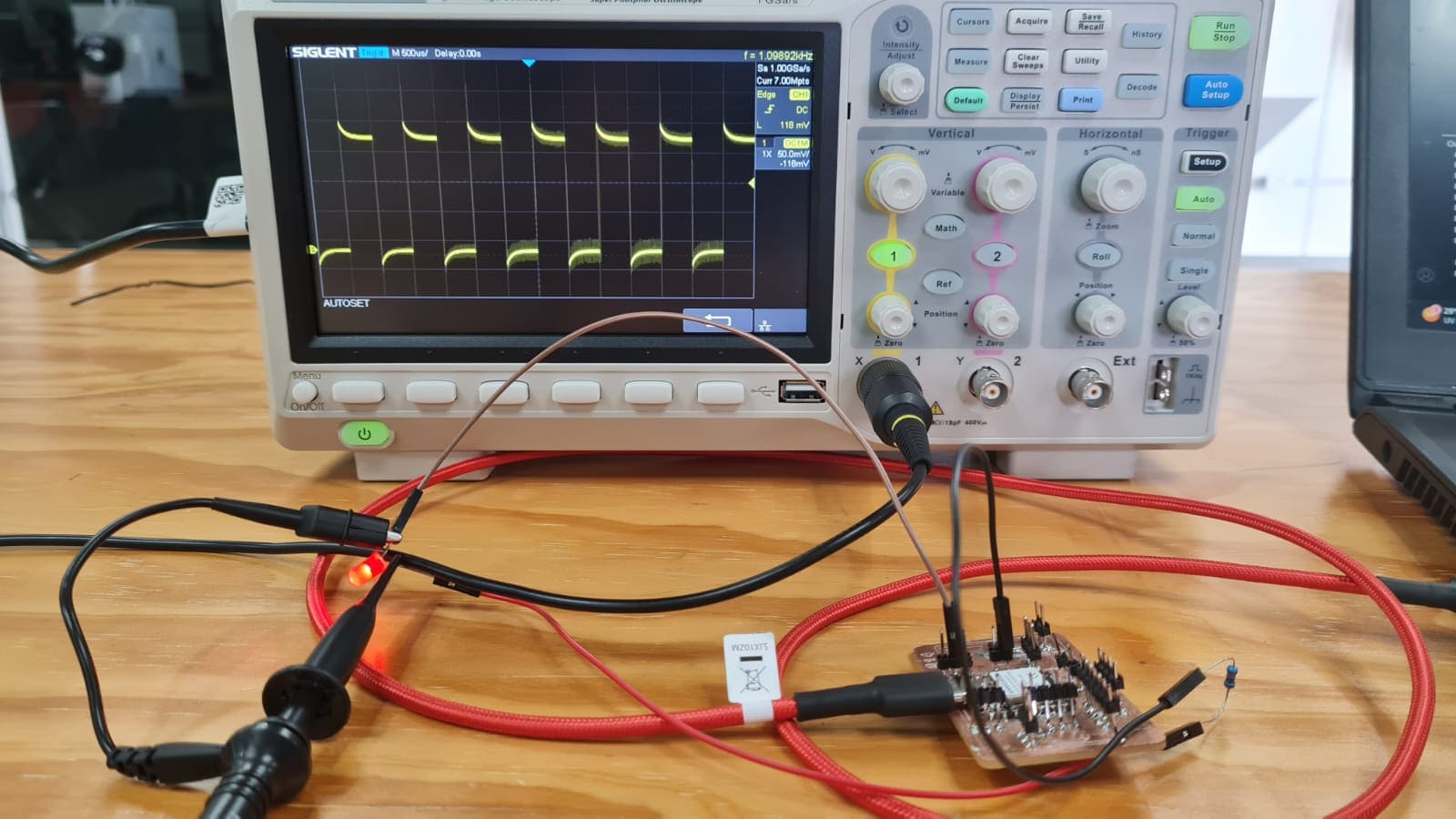
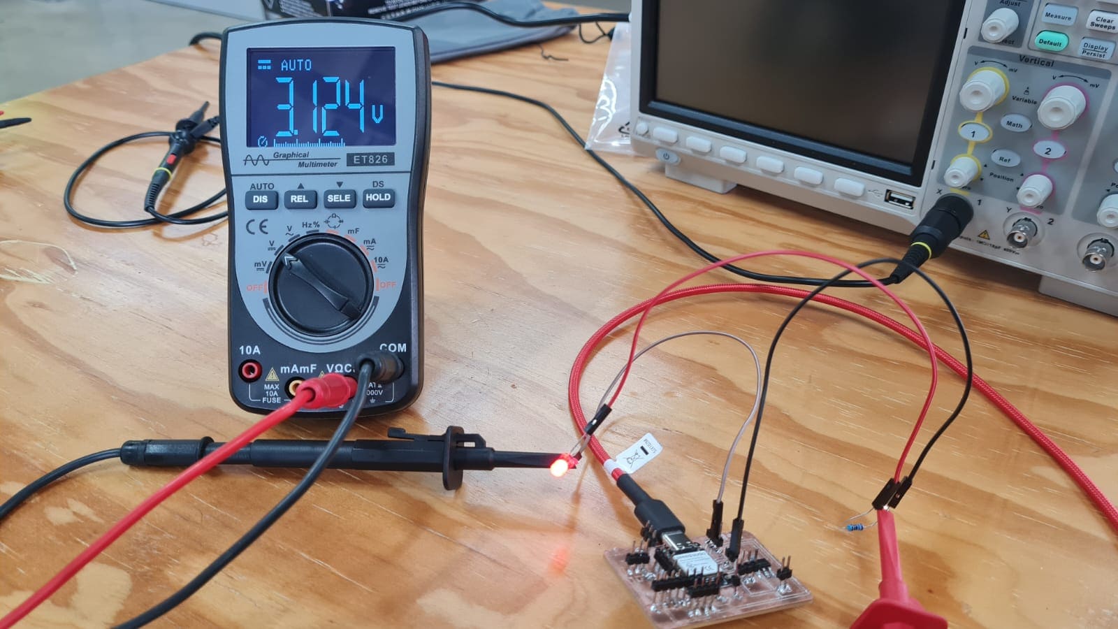
For the second results im still using the flashing led code and input a 3.3 voltage:
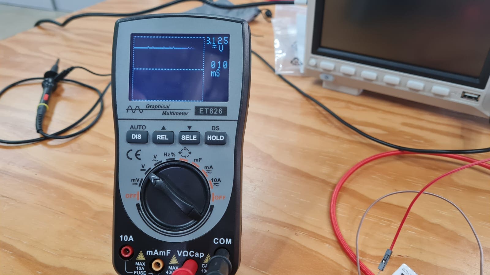
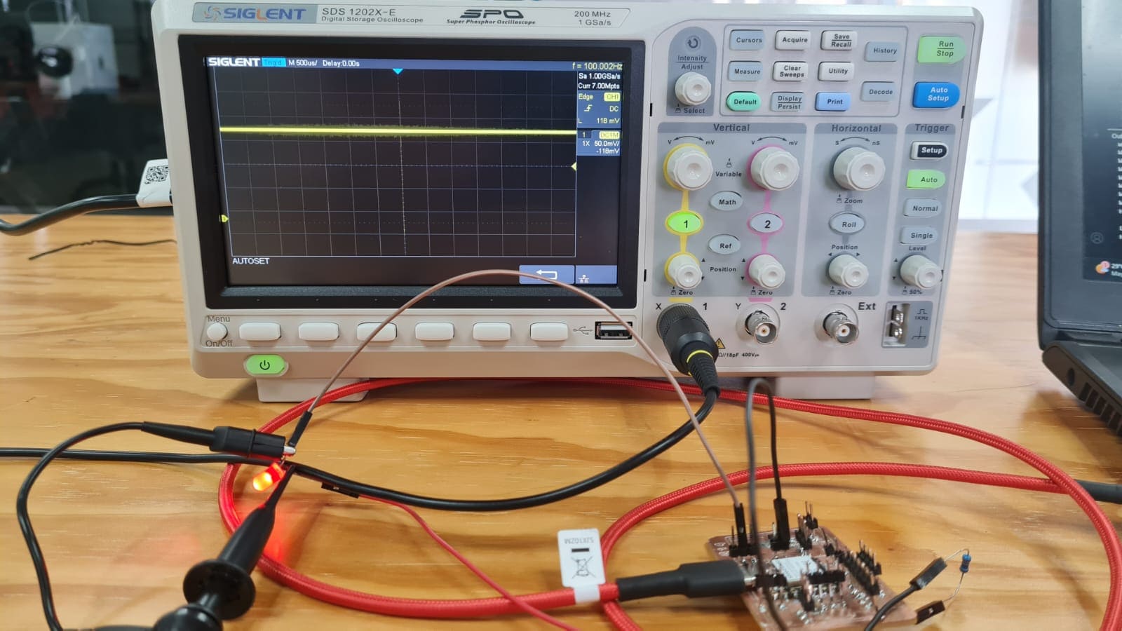
Here are some video of the results I got using the multimeter and the oscilloscope:
As I did and told in the measurements, it's important to learn about a few thing before starting our assignments. So I had to learn about connections in parallel and series. This is going to help me know how and why to connect the outputs devices to my circuit.
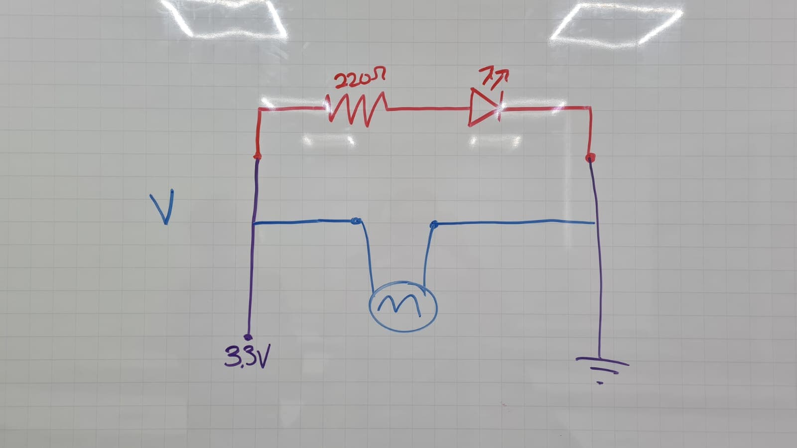
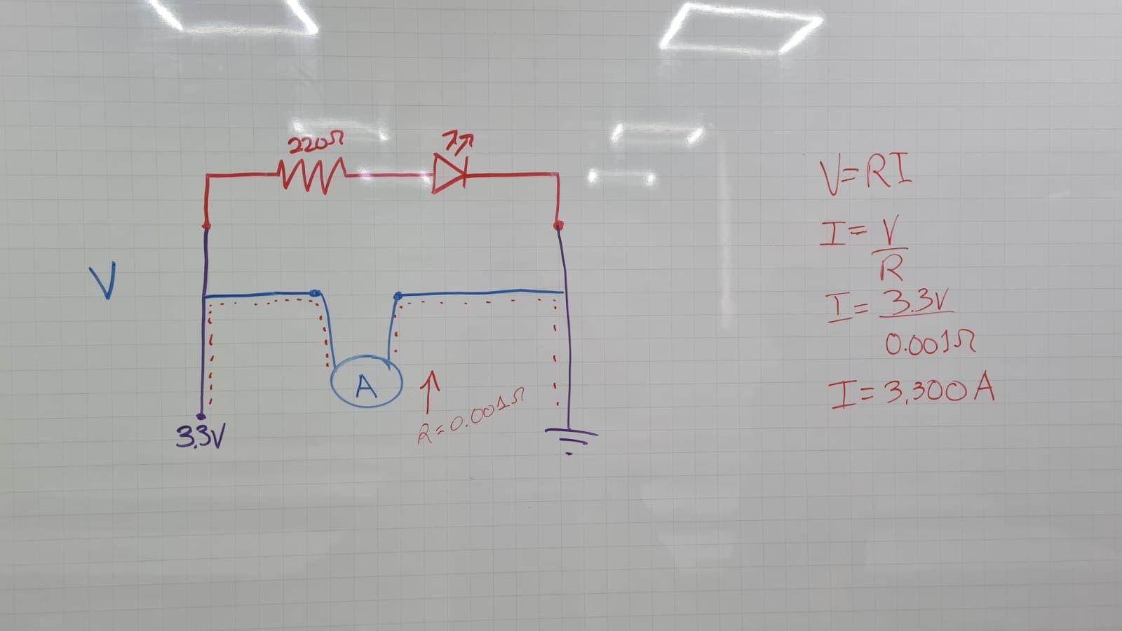
For this assignments i'm using the PCB board and circuit I design last week. This will help me connect the output devices and making sure the soldering is ok. For the my output devices i'm using:
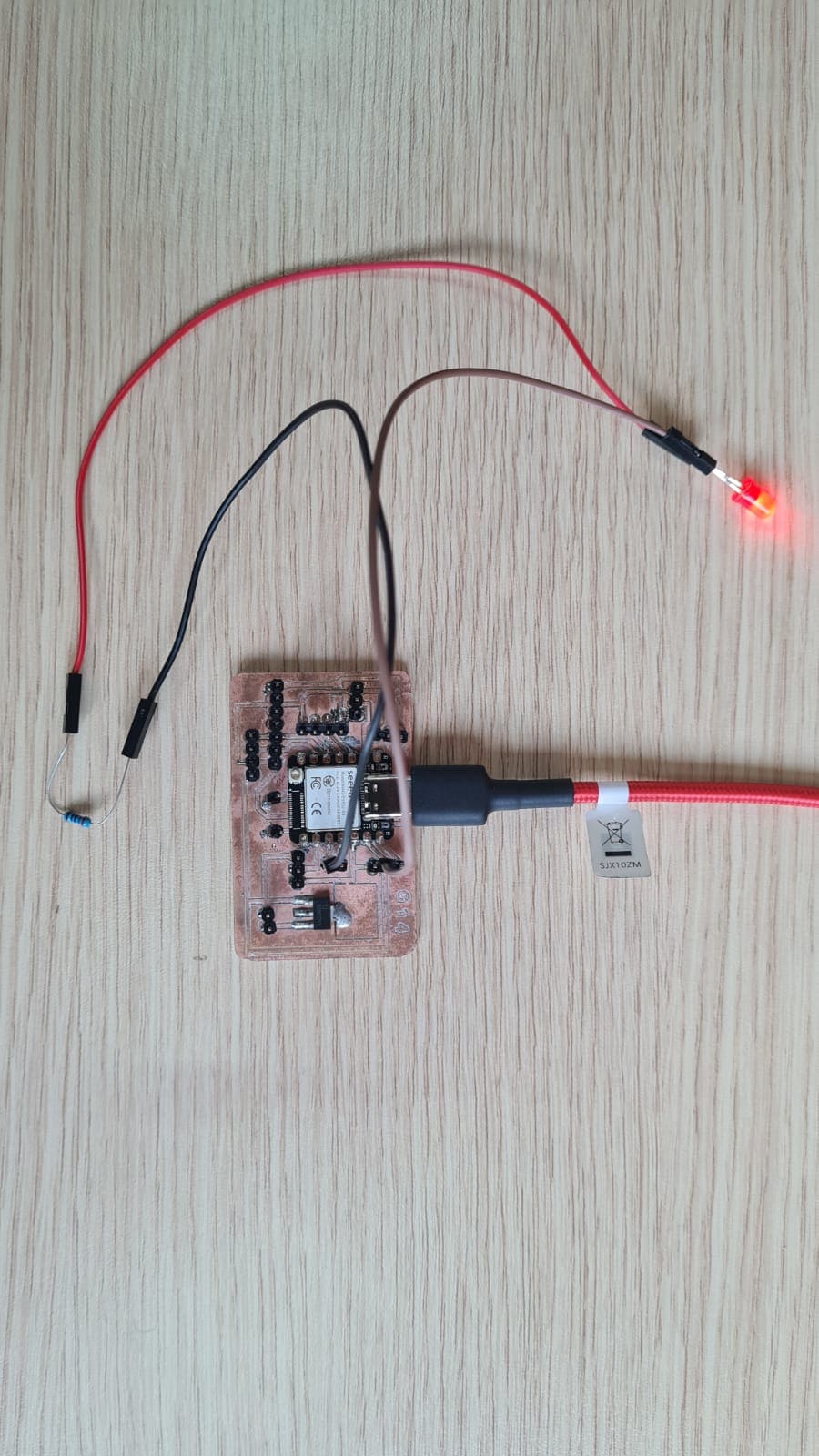
In my first individual task I use my circuit, a led and a code to make the led flash.
For this part I use:
How did I connect it?
For the second individual task I use my circuit, a Oled screen and a code to print a text in the screen.
For this part I use:
How did I connect it?

In this part I share the code I use for the led and screen.
In the code I set 4 led because I used it for the protoboard connection and then I define some parts as comments to use it when I connected the led directly to the circuit.
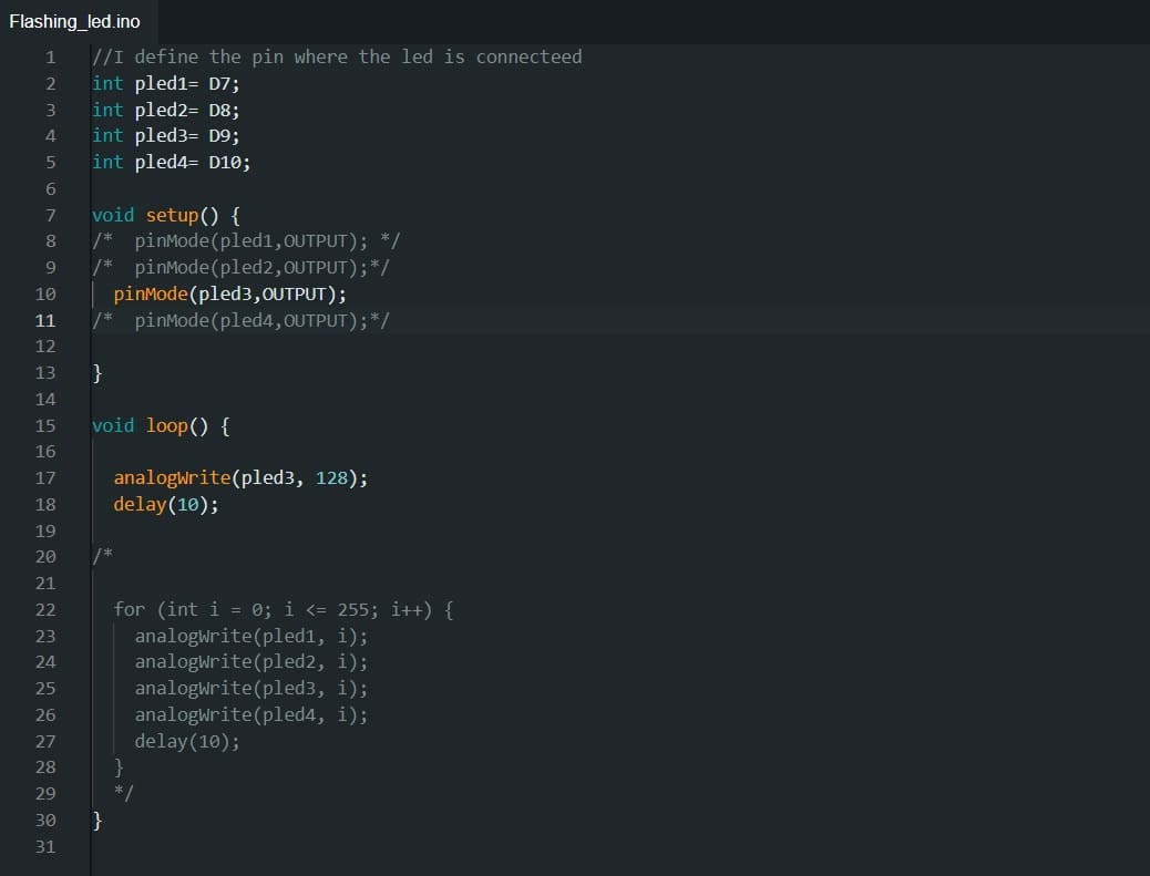
In the code I connected 4 pins:
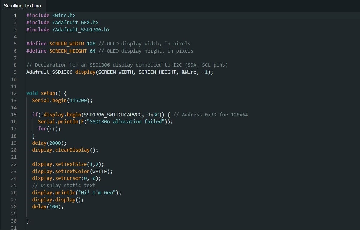
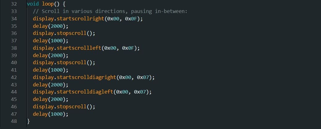
In this part you can download the files that I use for this 9th week assignments.
What did I learn in this week?